
Learn the Secrets of Analogue-to-Digital Converters
Data acquisition systems capture real-world signals and convert them into a format that a computer can understand. Many signals - such as temperature, pressure and strain - will originally be analogue. These need converting to a digital signal before being transferred to the computer. This is done by an analogue-to-digital (A/D) converter.
This article explains the meaning of the terms that hardware manufacturers use when describing their analogue-to-digital converter.
Range
The input (or gain) range refers to the maximum and minimum voltage that will be digitised by the A/D converter. An input may be bipolar, covering a range of -10 mV to +10 mV for example; or unipolar, perhaps covering a range of 0 to 10 volts. Many systems offer a choice of ranges, and you can select the most appropriate using software like Windmill. It's best to choose the smallest range that encompasses your signal, as this optimises the resolution.
Resolution
The resolution of the A/D converter is the number of steps into which the input range is divided. The resolution is usually expressed as bits (n) and the number of steps is 2n-1 (which equates to 2n values). A converter with 12-bit resolution, for instance, divides the range into 212, or 4096, values. In this case a 0-10 V range will be resolved to 2.5 mV, and a 0-100 mV range will be resolved to 0.025 mV. Although the resolution increases when you narrow the range, there is no point in trying to resolve signals below the noise level of the system: all you will get is unstable readings. Some A/D converters have a choice of resolutions (offering 12-, 13-, 14-, 15- and 16-bit for example). You can choose the most suitable for your application, balancing speed against accuracy.
Successive Approximation Converter
A technique used in some types of analogue-to-digital converters to quickly measure a momentary value of the analogue signal. It compares the signal with progressively smaller values, each step getting nearer to the actual voltage. The converter first compares the signal against a voltage which is half the input range. It keeps the half if the analogue input signal is above that level and adds a quarter of the input votage before comparing again. Twelve such steps will give 12-bit resolution.
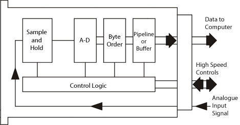
Successive approximation analogue-to-digital converter diagram
Conversion takes place in four stages
- The analogue signal is frozen in the sample and hold circuit
- It is converted to a digital number
- The order in which the two bytes required for this number will be sent to the computer is selected
- The two bytes are placed into either a pipeline or buffer store.
A pipleline store lets the converter do another conversion while the previous data is transferred to the computer. A buffer lets values accumulate to be read by the computer when convenient. This frees the computer from having to deal with the samples in real time, allowing them to be processed in batches without losing any data.
Sample and Hold Acquisition Time
A sample and hold circuit freezes an otherwise varying analogue voltage at the moment the sample is required. This voltage is held constant whilst the A/D converter digitises it. The acquisition time is the time between releasing the hold state and the sample circuit settling to the new input voltage. Sample and hold circuits are not used with integrating converters.
Flash Analogue-to-Digital Converter
Like the successive approximation converter, this works by comparing the input signal to a reference voltage. A flash converter though, has as many comparators as there are steps in the comparison. So an 8-bit converter has 28 or 256 comparators. This makes an extremely fast converter.
Integrating Analogue-to-Digital Converter
An integrating A/D converter averages the analogue input signal over a period of time. This helps to reduce noise. It is a slow method of conversion and is suitable when the signal to be measured fluctuates slowly, as in the case of a temperature monitored by a thermocouple.
In a Dual Slope Integrating Converter for example, the input signal charges a capacitor for a fixed period. The capacitor is then allowed to discharge at a fixed rate and the time to fully discharge the capacitor is measured. This time is a measure of the integrated input voltage.
Another type of integrating A/D converter is a Charge Balancing Converter. Here the input signal charges a capacitor for a fixed period, but in this case the capacitor is simultaneously discharged in units of charge packets. (Meaning that if the capacitor is charged to more than the packet size it will release a packet, if not a packet cannot be released.) This creates a pulse train. By counting the pulses coming out of the capacitor, the system determines the input voltage. A charge balancing converter is also known as a voltage to frequency converter.
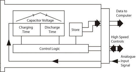
Dual slope integrating analogue-to-digital converter diagram
Integration Time
The time over which an integrating A/D converter averages the analogue signal. In countries with a 50 Hz mains supply, a 20 millisecond integration time will average over a complete mains cycle - helping to reduce mains frequency interference. You can use Windmill software to choose the integration time for many data acquisition systems
Conversion Time
The time taken to convert an analogue signal to a digital signal.
Throughput
Throughput is the maximum rate at which the A/D converter can acquire and transfer data values. Roughly speaking, it will be the inverse of the (conversion time + the acquisition time) of the A/D converter. Thus a converter that takes 10 microseconds to acquire and convert will be able to generate about 100000 samples per second.
Throughput can be increased if a second conversion can start while the first is still in progress. Throughput may be slowed down, however, by other factors which prevent data transfer at the full rate. For example, signals which are switched (multiplexed) into the converter may need time to settle - especially highly amplified signals or signals from high impedance sources.
The throughput of an integrating converter however isn't the inverse of the integration time. It also depends on the maximum discharge time.
Linearity
Ideally an A/D converter will convert the input range into equal steps. In practice the steps are not exactly equal, which leads to non-linearity in a plot of A/D output against analogue input signal.
Offset Errors
Offset is where you get a reading other than zero for a zero condition: every reading will be inaccurate by this amount. Offset errors are minimised by including signal conditioning circuits before the A/D converter in the system.
Re-Calibration
Some A/D converters are able to re-calibrate themselves periodically. They measure a reference voltage and compensate for offset and gain drifts. This is useful for long term monitoring as it prevents drifts from accumulating. If the re-calibrations are set too far apart, there may appear to be small discontinuities in the recorded data as the re-calibrations occur.
Drift occurs because of temperature changes, and because component values change over time.
Drift is usually only significant if you are trying to measure low-level signals - a few millivolts - over long periods of time or in difficult environmental conditions. In these cases look for self-calibrating systems.