
Monitor - ISSN 1472-0221
The Newsletter for PC-Based Data Acquisition and Control
Issue 249, June 2019
Welcome to Monitor - the data acquisition and control newsletter. Any comments or questions email monitor@windmillsoft.com. You can download this issue as a pdf file from https://www.windmill.co.uk/monitor/monitor249.pdf.
Contents
* Round-the-Clock Product Testing
* Your DAQ Questions Answered: Strain logging at sea
* Data Acquisition News Round-Up
Round-the-clock Product Testing
Continuous, long-term, testing ensures the safety and suitability of electrical and mechanical products. Round-the-clock monitoring, with automatic shut down should a danger level be crossed, is a common task for an unattended data acquisition system. For the majority of products the same general principles apply. Here we illustrate those principles with two specific examples. Let's look first at internal combustion engines and then at electric light switches.
Switch Testing
Our second example is testing electric light switches, like those on the walls of your house or office. We measure the temperature of a switch, making sure it doesn't get too hot, and the voltage drop across the switch. Ideally the temperature would remain constant and the voltage at both ends of the switch would be identical. In practice, because contact wear and switch oxidation increase resistance, the temperature will increase and the voltage drop.
Durability and Performance Testing
A pneumatic finger, under software control, mechanically presses the switch on and off. The duty cycle of switch testing is typically: switch on for 4 seconds and switch off for 6 seconds. Whereas in our engine testing example the duty cycle lasted an hour, in switch testing it lasts for 10 seconds. This cycle is repeated 30 000 times.
Periodically, at 25%, 50%, 75% and 100% through the test, the software leaves the switch on for an hour and records the rise in temperature and voltage drop across the contacts.
Like in the engine testing example, the temperature is measured with a thermocouple. In this case the thermocouples are mounted on the contacts at mains voltage, and so must be isolated.
Automatic Shut Down
As well as counting the number of pneumatic finger operations, the software counts the number of voltage state changes (on-off). These two counts should be identical, ensuring that the arm is not missing the switch and that the switch is still functioning. If the counts differ, indicating that the switch has not been switched on or off, the software automatically stops the test.
It will also stop the test for safety reasons - should the temperature become too hot for example.
Permanent Records
The software records all the measurements, counts and alarms. These can be automatically passed, to, say, a spreadsheet for analysis and a copy printed suitable for the standards inspectorate.
Tractor Engine Testing
Durability and Performance Testing
The test procedure runs the engine slowly for part of every hour, and at full speed for the rest of the hour. The timings simulate the typical use of the engine: a tractor engine might be idly ticking over for 55 minutes and at full speed for 5 minutes for example. This is called the duty cycle and measures durability (tickover) and performance (full speed).
Making the Measurements
During the length of the test, which is often several months, a range of measurements are taken. These include fuel consumption, fuel temperature, top hose temperature, oil pressure, torque, exhaust back pressure, engine speed and smoke test.
Transducers convert signals from the engine into a form the data acquisition hardware can understand - normally voltage but sometimes current.
Temperatures are often measured with K-type thermocouples. These are robust and cheap, and sufficiently accurate for the task.
Speed is measured in revolutions per minute by a tachometer. This produces either a voltage output, or a pulse output. You need a counter interface module to handle the pulse output.
You wire the transducers to the data acquisition interface. This is often remote from the computer and connected to it over an RS485 cable. RS485 allows long distances between the test site and the PC (around 1000 metres) - protecting the PC from unsuitable environments. It also lets you distribute several data acquisition devices around the site, connecting them all to one cable and computer. It is quite a slow communication link (handling around 35 samples per second), but for product testing such as this high speeds are not needed.
Software Control
How often measurements are taken from the engine, and what happens if a measurement exceeds its danger level, is controlled by the software. If, say, 6 engines are being tested by one PC, the software typically logs around 200 measurements every minute. Once an hour the software tells the engines to increase speed to maximum revolutions. It does this by sending control signals down analogue output channels. After a specified time it tells the engine to return to tickover speed. The software provides permanent records of how key parameters have changed, highlighting any long term drifts. Importantly, the software shuts the engine down should, say, oil pressure be lost - saving the engine from irrevocable damage.
Five Principles of Product Reliability Testing
Although we have discussed two very different products, the method of testing is very similar in each.
- The tests are controlled by software, with automatic shut-down should alarm levels be crossed.
- The software saves permanent records, suitable for proving the reliability of the product to government standards organisations.
- The tests are 24 hours a day, long term (around 6 months for engines) and unattended.
- The tests each have a "duty cycle": operating at different states over a period of time. One hour for engines and ten seconds for switches.
- Durability and performance are both tested, either as part as the duty cycle (engines) or by periodically interrupting the duty cycles (switches).
For more details of product reliability testing, or to discuss your application, please contact Windmill Software at sales@biodataltd.com.
Your Data Acquisition Questions Answered: Strain Logging at Sea
Question
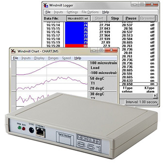
I have a couple of questions about your Microlink 851-SG: Strain Data Logger. Does the package include everything I need to calculate strain? I already have some 350 ohm strain gauges wired up is it just as simple as plugging the gauges into the device and away I go?
The features say it can be used stand alone. Does this mean it is able to be set up using a PC then disconnected and it will continue to run when it is powered up? Does the logger remember its settings? So every time the craft is turned on it will restart recording the strain?
The memory is stated as 65000 scans. Is this per channel or in total?
Answer
The 851-SG converts single gauge readings to strain. You would need to tell the software the configuration you are using, for example quarter-bridge configuration. Once setup the Microlink 851 can log the data values at intervals from 0.1 seconds up to several hours.
It does hold the settings and start logging again when powered up. You would need to connect your laptop through an ethernet cable to download the data.
Each scan is all the channels, so if you had 16 channels the logger would store 104000 data points before overwriting the earliest data.
More details are at Microlink 851-SG: Strain Data Logger.
DAQ News Round-up
Welcome to our round-up of the data acquisition and control news. If you would like to receive more timely DAQ news updates then follow us on Twitter - @DataAcquisition - or grab our rss feed.
'Pete the plant' to take selfies to help monitor its environment
New system allows plants to take "selfies" through the power of microbial fuel cells with the ultimate aim of using them to power camera traps and sensors in the wild
Source: Engineering and Technology
https://eandt.theiet.org/
Boaty McBoatface mission gives new insight into warming ocean abyss
The first mission involving the autonomous submarine vehicle Autosub Long Range (better known as 'Boaty McBoatface') has for the first time shed light on a key process linking increasing Antarctic winds to rising sea temperatures
Source: University of Southampton
https://eurekalert.org/
Food freshness sensors could replace 'use-by' dates to cut food waste
Academics have developed low-cost, smartphone-linked, eco-friendly spoilage sensors for meat and fish packaging.
Source: Imperial College London
https://www.imperial.ac.uk/
* Copyright Windmill Software Ltd
* Reprinting permitted with this notice included
* For more articles see https://www.windmill.co.uk/
We are happy for you to copy and distribute this
newsletter, and use extracts from it on your own web
site or other publication, providing the above notice
is included and a link back to our website is in place.
For previous issues by subject see https://www.windmill.co.uk/monitorindex.html
SUBSCRIBING OR CANCELLING SUBSCRIPTION Visit https://www.windmill.co.uk/newsletter.html and add or remove your e-mail address.
Windmill Software Ltd, PO Box 58, North District Office,
Manchester, M8 8QR, UK
Telephone: +44 (0)161 834 6688
Facsimile: +44 (0)161 833 2190
E-mail: monitor@windmillsoft.com
https://www.windmill.co.uk/
https://www.windmillsoft.com/