Temperature Measurement: Thermocouples or RTDs?
Measuring Temperature with a Computer | Comparison of Thermocouples and RTDs | Thermocouples - Rugged, Versatile and Low Cost | RTDs, PRTs, thermistors, Pt100 - Accurate and Stable | Hardware and Software to Measure Temperature | Comments
Measuring Temperature with a Computer
Temperature measurement is the most common application of data acquisition systems. You will need a device to measure the temperature - a temperature sensor. Thermocouples, resistance temperature devices (RTDs), thermistors, platinum resistance thermometers and infrared thermometers are all types of temperature sensor. The most popular are thermocouples and RTDs. The sensors you choose depends on several things, such as as your expected maximum and minimum temperatures, cost, accuracy needed and your environmental conditions.
To get data from the temperature sensor into your PC you need a data acquisition interface with suitable software. The interface unit plugs into your computer, for example into the USB or Ethernet port. You wire the sensor to the interface, install the software and the computer can now monitor temperatures.
Comparison of Thermocouples and RTDs
|
Thermocouple Measurement
Thermocouples are popular temperature sensors because they are cheap, versatile and sturdy. They comprise two dissimilar metals joined together, making a continuous circuit. If one junction has a different temperature to the other, an electromotive force (voltage) is set up. This voltage varies with the temperature difference between the junctions. If the temperature at one junction is known, the temperature at the other junction can be calculated.
Types of Thermocouple
There are several types of thermocouple, labelled with letters
according to their constituent metals. A K-type thermocouple, for
example, is made up of chrome and Alumel. The metals give the
thermocouples differing properties, such as temperature ranges and
accuracy.
Potential Pitfalls in a Computerised Thermocouple System
- The "Cold Junction" Reference Measurement
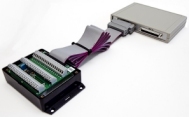
The system depends on knowing the temperature of one of the thermocouple junctions (the cold junction). Housing this junction in an isothermal box will keep the temperature constant, and a cold junction sensor in the box will tell the system the temperature. The isothermal box sits beside the computer. You would connect the thermocouple wires to screw terminals in the box, and connect the terminals to, say, a USB data acquisition unit using a ribbon cable. - Attaching the Thermocouples to Metal Surfaces
If the thermocouples are directly attached to a metal surface, particularly one carrying its own voltage such as a heating element, you need to isolate the signals. This will prevent high voltages in the monitored item damaging the data acquisition equipment. It will also make the measurements "floating", letting you record the small thermocouple voltage in the presence of high voltages. - Linearisation
The voltage produced by a thermocouple does not change linearly with temperature - presenting a problem for the data acquisition system. A good solution is to use software to obtain the correct temperature in, say, oC or oF. Windmill software, for example, will do this for you automatically, with built-in linearisation for B-, E-, J-, K-, N-, R-, S- and T-type thermocouples. - Using the Wrong Type of Thermocouple Lead
You need to connect the thermocouple to the data acquisition equipment using the correct type of extension or compensating lead. This is made of either the same material as the thermocouple metals, or material with similar characteristics. - Long Thermocouple Leads - Noisy Signals and Added Wiring Costs
Thermocouple leads are often many metres long, and have a higher resistance than normal copper wire. This means that the leads can act as aerials, picking up environmental electrical noise that contaminates the voltage signal. It might also mean expensive wiring costs. In this case you need either to take precautions against noise, or distribute data acquisition units - placing them close to the thermocouples on Modbus, RS485 or Ethernet networks for example.
RTD Measurement
Resistance temperature devices (or detectors) rely on the principle that the resistance of a metal increases with temperature. For extreme precision, the resistance element is made of platinum and the RTD is known as a platinum resistance thermometer (PRT). When specified to have a resistance of 100 Ohm at 0 oC, RTDs may be referred to as Pt100 probes. When the RTD has a semiconductor resistance material it is called a thermistor. Thermistors are very sensitive but also the most nonlinear of the RTDs with a negative temperature coefficient.
Potential Pitfalls in a Computerised RTD System
- Errors Arising from Lead Resistance
When the resistance to be measured is small, the resistance in the leads to the RTD can significantly affect accuracy. Several methods exist for monitoring RTDs, which address the problems associated with lead resistance. These methods include balanced bridges and constant current sources.
Constant current source measurements give excellent results for all wiring configurations, including 2 wire, 3 wire, 4 wire and 4 wire compensated. The most accurate results are obtained using a 4 wire arrangement. Each RTD requires the data acquisition hardware to provide a constant current source. The current flows through the RTD and the voltage drop over the RTD is measured. Using Ohms law the value of the resistance of the RTD can be calculated.
- Converting the Resistance to a Temperature
Software like Windmill automatically converts the resistance measurement to a temperature in your choice of engineering units.
Hardware and Software to Measure Temperature
Windmill Software offer several temperature measurement packages. To measure temperature using thermocouples we recommend either the Windmill 751-TC package, which connects to a computer over USB, or the Microlink 851-TC package, which connects over Ethernet or Internet. These comprises Windmill data acquisition and control software together with a measurement & control unit and isothermal box. With additional hardware RTDs and other signals can also be measured: strain, pressure, resistance, etc.
For RTD temperature measurement we offer the Windmill 752-RTD package, which connects over USB. The 752 USB unit provides differential inputs to monitor up to 8 RTDs or Pt100 probes, and up to 16 voltage signals. You can connect 8 USB units to 1 PC. The units also provide digital input and output, counting, and voltage or current output. The system supports 2 wire, 3 wire, 4 wire and 4 wire compensated resistance measurement.