
This article tells you just about everything you need to know to get a RS232 connection working between your computer and your measuring device or instrument. It starts by discussing the RS232 standard and continues with the various pin connections available. The next section gives a step-by-step guide to getting communications working: testing the different elements of the system. Finally there are suggestions for further reading and you are invited to send us your comments or questions.
The Ins and Outs of RS232 | Testing Serial Port Communication | Status of the COM Port Lines | DTR High: Removing Handshaking | Further Reading | Comments or Questions?
RS232 Connections
RS stands for recommended standard. In the 60's a standards committee now known as the Electronic Industries Association developed an interface to connect computer terminals to modems. Over the years this has been updated: the most commonly used version of the standard is RS232C (sometimes known as EIA232); the most recent is RS232E. The standard defines the electrical and mechanical characteristics of the connection - including the function of the signals and handshake pins, the voltage levels and maximum bit rate.
If RS232 is a standard why can't I just use a standard lead to connect together two RS232 ports and expect them to talk to one another? That's a good question. The answer is that the RS232 standard was created for just one specific situation and the difficulties come when it is used for something else. The standard was defined to connect computers to modems. Any other use is outside of the standard. The authors of the standard had in mind the situation below:

The standard defines how computers (it calls them Data Terminal Equipment or DTEs) connect to modems (it calls them Data Communication Equipment or DCEs). The standard says that computers should be fitted with a 25 way plug whilst modems should have a 25 way D socket. The interconnecting lead between a computer and a modem should be simply pin1-pin1, pin2-pin2, etc. The main signals and their direction of flow are described below. It is important to note that a signal which is an output from a computer is an input to a modem and vice versa. This means that you can never tell from the signal name alone whether it is an input or an output from a particular piece of equipment. Also, instead of being a DCE device, a data acquisition device might be configured as DTE. In this case you need an adaptor or the RS232 cable wired differently to normal. When the PC is connected to a DTE instrument - called a null modem arrangement - some of the cable wires must cross over.
RS232 Pin Connections
TXD Transmitted Data, Pin 2 of 25 way D
This is the serial encoded data sent from a computer to a device.
RXD Received Data, Pin 3 of 25 way D
This is the serial encoded data received by a computer from a device.
DSR Data Set Ready, Pin 6 of 25 way D
This should be set true by a device whenever it is powered on. It can be read by the computer to determine that the device is on line.
DTR Data Terminal Ready, Pin 20 of 25 way D
This should be set true by a computer whenever it is powered on. It can be read by the device to determine that the computer is on line.
RTS Request to Send, Pin 4 of 25 way D
This is set true by a computer when it wishes to transmit data.
CTS Clear To Send, Pin 5 of 25 Way D
This is set true by a device to allow the computer to transmit data. The standard envisaged that when a computer wished to transmit data it would set its RTS. The local modem would then arbitrate with the distant modem for use of the telephone line. If it succeeded it would set CTS and the computer would transmit data. The distant modem would use its CTS to prevent any transmission by the distant computer.
DCD Data Carrier Detect, Pin 8 of 25 Way D
This is set true by a modem when it detects the data carrier signal on the telephone line..
PC Serial Ports (DTE)
A nine pin D plug has become the standard fitting for the serial ports of PCs, although it's nothing to do with the RS232 standard. The pin connections used are:
| Pin | Direction | Signal |
| 1 | Input | DCD Data Carrier Detect |
| 2 | Input | RXD Received Data |
| 3 | Output | TXD Transmitted Data |
| 4 | Output | DTR Data Terminal Ready |
| 5 | Signal Ground | |
| 6 | Input | DSR Data Set Ready |
| 7 | Output | RTS Request To Send |
| 8 | Input | CTS Clear To Send |
| 9 | Input | RI Ring Indicator |
9-Way Pin to 25-Way Pin
| DB9 | DB25 | Signal | |
| 1 | 8 | DCD | Data Carrier Detect |
| 2 | 3 | RXD | Received Data |
| 3 | 2 | TXD | Transmitted Data |
| 4 | 20 | DTR | Data Terminal Ready |
| 5 | 7 | Signal Ground | |
| 6 | 6 | DSR | Data Set Ready |
| 7 | 4 | RTS | Request To Send |
| 8 | 5 | CTS | Clear To Send |
| 9 | 22 | RI | Ring Indicator |
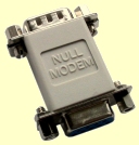
Null Modem Connections
Instead of being a DCE device (see above for details), a data acquisition device might be configured as DTE. In this case you need an adaptor or the RS232 cable wired differently to normal. When the PC is connected to a DTE instrument - called a null modem arrangement - some of the cable wires must cross over. For example, when there is no hardware handshaking in place the connections are as follows.
| DB9 | DB9 | Signal |
| 2 | 3 | RXD Received Data - TXD Transmitted Data |
| 3 | 2 | TXD Transmitted Data - RXD Received Data |
| 5 | 5 | Signal Ground |
Testing Serial Port Communication
You've plugged your instrument into your computer's COM port, installed your data acquisition software, but no data appears. You suspect it is a problem with your RS232 communications. What do you do?
Download the free ComDebug serial port monitor software. This provides many features which let you detect, and correct, communication errors. Please note that we can't offer free technical support for the free software - if you need help using it click the program's Help button or see this web page.
If you can't immediately obtain data from your device with ComDebug, follow these steps.
1. Find Communication Details: Baud Rate etc.
Obtain all the information available about your instrument or device. You will need to know the number of the com port into which you have plugged your device, the device baud rate, number of bits in the data byte and parity. Enter this information in ComDebug. If you have information about the Stop Bits then use it, otherwise set them to 2. This will at worse slow the message down slightly. See Making Measurements through the COM Port for a detailed explanation of each of these settings.
If you are using a virtual com port, for example with a USB-RS232 adaptor, open the Device Manager from Windows Control Panel to find the number of the com port that Windows has assigned to your device. Tips on Using USB-to-Serial Converters gives more information.
2. Send a message
If you can persuade your device to send a message, perhaps a power on message or a message that can be initiated by a button press, then do so. This will verify your signal connections. At this stage you should select the no handshake option when setting up the COM Port. If you still can't receive any data, you may have a wiring error. Use the ComDebug program's COM Port Status window to check the state of the lines to and from the computer, and see points 3, 4 and 5 below.
3. Check the COM port is Working Correctly
This loopback test works if your instrument is a DTE computer type with a 9-pin connector. (See above for more on DTE type instruments).
- Disconnect the RS232 cable from your instrument and check it has a socket on the free end.
- Unravel a paperclip, insert one end into the pin 2 hole on the cable socket and the other into the pin 3 hole. (Pin 1 is to the right of the long edge, pin 2 is next to it.)
- Send a message. It should echo back to the computer, confirming that messages are arriving at your instrument and the COM port is working correctly.
4. Check the Cabling
If you suspect a wiring error, you could try contacting the manufacturer of your instrument to see if they sell the correct cable. Sartorius devices, for example, won't work with a standard RS232 cable and you need to either purchase a cable from the company or re-wire the connections. If your instrument is a DTE computer type, you may need a Null Modem adaptor. Alternatively, you may want to try rewiring the cable connector yourself.
When wiring the cable yourself, The first signals to connect are the ground, RXD and TXD. Try to establish, from your device's documentation, which signal wire carries its output data - connect this to the computer's RXD. The signal which inputs data to your device should be connected to the computer's TXD. Don't rely on the signal names, remember the signals can be either inputs or outputs depending on whether your device is a computer or modem type. It's not unusual for Instrument Manuals to neglect this vital information, but you may be able to get a clue from other signals. For instance if the manual says that DTR is an output then the instrument should be a computer type. If on the other hand it says that DSR is an output then it should be a modem type. In fact if you know the direction of any one of the signals you should be able to deduce the rest. Be careful when doing this: we have encountered manufacturers who change the names of the data signals when dealing with modem types - after all it must be confusing to tell a user that Transmitted Data is an input.
If the signals are correctly named then a computer to modem link connects TXD to TXD and RXD to RXD. A computer to computer link (more common when dealing with instruments) connects TXD to RXD and RXD to TXD. This crossed arrangement is sometimes called a Null Modem connection, and buying an adaptor may solve your wiring problems.
If all else fails you can determine which data signal is the output by measuring the unconnected data lines with a voltmeter or using one of the plugs with built in LED indicators which show the line state. The output signal will be at a definite negative voltage, properly -12 Volts or more. The input line will be close to 0V. The only time this strategy will fail is if your device is of the multidrop variety. These only drive the output line for the duration of the transmitted message.
5. Set Hardware Handshaking or Flow Control
If you are confident that the signal wires are properly connected, but you still can't retrieve a message from your instrument, you may need to tie the handshake lines.
Handshake arrangements can be used for 2 purposes. Firstly the computer can prevent the device from sending data when it is not able to receive it. Secondly the device can prevent the computer from sending data when it is not ready for it. The fact that your device comes equipped with inputs and outputs that can be used for handshaking is no guarantee that handshaking is needed. The signals are often provided simply because the processor used in the device provides them, so the manufacturer feels he may as well put them on the plug. It is usually best to start with the intention of tieing any potential handshake lines to fixed voltages so that they do not affect operation. In fact many manufacturers add tieing resistors to handshake lines so that if you do not want to use them you simply make no connection.
If you start with no handshaking what symptoms might indicate that it really is needed ?. Well one possibility is that the computer misses part of a message because its input buffer overflows. In COMIML the buffers are 3000 bytes long so you are unlikely to be bothered by this problem. The other possibility is that the device misses part of a message sent by the computer. This will presumably cause the device not to operate as desired. If you do decide that handshaking must be used then COMIML uses DTR / CTS handshaking. This means that the computer uses its DTR output to indicate when it is able to receive data and its CTS input can be controlled by the device to prevent transmission of data from the computer. Once you select the hardware handshake option the state of the CTS input to the computer becomes important. When hardware handshake is not selected the CTS line state is ignored, the DTR output however is maintained permanently high so you can use it to tie unused inputs on your device. If your instrument needs DTR to be low, see below.
6. Set Software Handshaking or Flow Control
Xon \ Xoff Handshaking is a software protocol that is often used to control data flow. Supposing that the computer were sending data to a device which could accept no more data for the time being - the device would send the single Xoff character to the computer which would stop sending data until it received an Xon character to restart transmission. The same arrangements would apply for the reverse direction of data flow. If your device requires this type of handshaking then simply select it in ComDebug.
Status of the COM Port Lines: Serial Port Software
In ComDebug's Terminal screen, select the Status button. This shows you the state of the computer's COM port. If you are not receiving replies from the instrument this may help you identify the problem
Red indicates true or high, green false or low.
- CTS - Clear To Send
- If you are using Hardware Flow Control in your COM Settings, CTS must be true.
- DCD - Data Carrier Detect
- Should have no effect on data flow and will normally be false. If it is true you may have a wiring error.
- DSR - Data Set Ready
- Should have no effect on data flow and will normally be false. If it is true you may have a wiring error.
- RI - Ring Indicator
- Should have no effect on data flow and will normally be false. If it is true you may have a wiring error.
- COM Output Lines
- You can control the state of these lines - check your instrument's Manual for details of the settings it expects. (Remember, red indicates true or high and green false or low.)
- RTS - Request to Send
- This is set true by a computer when it wishes to transmit data.
- DTR - Data Terminal Ready
- This should be set true by a computer whenever it is powered on. It lets the instrument check that the computer is on line.
What to do when the Instrument needs DTR Low and RTS high: Removing the Handshaking
Some software, like the Windmill COMIML serial driver, use the DTR line for handshaking (flow control), setting it high to indicate that it is ready to receive data. Some instruments, though, need DTR to be low and RTS to be high before they will provide data.
In this situation you need to change the connections on the RS232 cable.
Connect pins 8 and 7 (i.e. CTS drives RTS)
Connect pins 1, 4, 6 This should maintain the DTR line in the correct state, by connecting it to DCD and DSR
This would normally be done at the instrument end rather than the PC end of the cable.
Also check that transmit at one end goes to receive at the other.