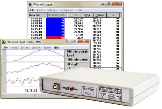
Data logging from strain guages to Windows software
The 751-SG package has lets you monitor 16 strain gauges, balanced bridges like pressure transducers and voltage signals. This unit also provides 32 digital inputs and outputs and 8 counters. Connect eight units to one PC and monitor 128 strain gauges.
The751-SG works over USB, for Ethernet or Internet connections see the 851-SG.
- Monitor strain gauges, or voltage signals, through 16 differential input channels
- witch up to 32 digital outputs
- Monitor up to 32 digital inputs
- Count events with up to 8 counters
- Options to also monitor temperature, pressure and current
- Includes the powerful yet easy-to-use Windmill Software for Windows: no programming required
- Connect up to 8 units to one PC, giving 128 strain or voltage inputs and 256 digital inputs and outputs
- Choice of four analogue input ranges, selected with Windmill software individually for each channel
- Alternatively, choose automatic ranging and let the software match the input signal as closely as possible
- Integrating analogue-to-digital converter reduces electrical noise
- Use Windmill to select the resolution of the A-D converter from 12- to 18-bits: choose high throughput or high resolution
- Automatic recalibration
- Free technical support for life
To order or discuss your strain measurement needs contact sales@biodataltd.com.
Strain Measurement
The Windmill 751-SG package lets you monitor strain gauge bridges and balanced bridges such as pressure transducers. You can configure individual channels to accept any of these inputs:
- voltage
- quarter bridge: single strain gauge
- half bridge: tensile + compressive strain gauge
- half bridge: normal + transverse strain gauge
- full bridge: 2 tensile + 2 compressive gauges
- full bridge: 2 normal + 2 transverse gauges
- full bridge: tensile normal + compressive normal + tensile transverse + compressive transverse gauge
Strain gauges need an external excitation voltage to supply sufficient current to keep all the bridge circuits energised. The 751-SG package provides four sets of 16 screw terminals giving + and - excitation and signals for each of 16 bridges. Two 1 kOhm termination resistors are mounted in half bridge configuration whilst high quality 350 and 120 Ohm resistors can be provided for the completion of quarter bridges.
When a bridge input is selected the Windmill software monitors excitation voltage and performs the bridge calculation to produce a reading in microstrain. This eliminates errors due to changes in excitation voltage.
The initial unstrained bridge measurement is often much larger than the change in signal due to strain. If this initial value is not accounted for, it restricts the resolution you can obtain - i.e. the smallest signal you can measure. Windmill software can zero or balance the bridge, nulling the offset of the initial voltage. So instead of measuring over a wide range, 0 to 0.5 V for example, you can choose a narrow range such as 0 to 0.01 V.
Each range is divided into a fixed number of steps: the resolution. The smaller the range and the larger the resolution, the more precise the reading. The 751-SG offers a choice of resolutions from 12-bit for fast sampling to 18-bit for greater precision.
We have more tips for computerised strain measurement here.
Digital Inputs and Outputs
The 751-SG provides 32 digital I/O lines, arranged in four groups of 8. Use Windmill to choose whether each group is an input or an output. You can read or set the state of each line individually. Alternatively, you can switch several channels at the same time.
Counters
The USB unit has eight 16-bit totalling counters. Each counter starts at zero and counts pulses to a maximum of 65535. You can reset a counter at any time from Windmill software. You can use the counters in two modes: accumulating count and resetting count. In accumulating count the counter keeps counting until you reset it. In resetting count the counter shows the number of pulses since the last reading.
You can set a scale and offset factor to the count from software. For example if the pulses came from a flow meter which produced one pulse for every 50 millilitres, a scale factor of 0.05 would give a reading in litres. The counters are found on 8 of the digital input and output lines. You can use any of these you don't need for counting as normal digital inputs: the counts are always maintained even if you don't plan to use them.Software
Data logging, charting, alarm indication, output control, process mimics and sequence control software is included.
Microlink 751-SG Specifications
| ANALOGUE INPUTS | ||
| Maximum safe input voltage: | ||
| Power supply on | ± 48 V | |
| Power supply off | ±33 V | |
| Transient | ±300 V | |
| Amplifier: | ||
| Ranges (V) | ±0.01, ±0.1, ±1, ±10 | |
| Common mode range | ±13 V | |
| Relative accuracy of ranges: | ||
| gain = 1000 | ±0.1% | |
| gain = 1, 10, 100 | ±0.05% | |
| Analogue to Digital Converter: | ||
| Maximum linearity error | ±0.02% | |
| Resolution | Integration Time | Samples/Second |
| 12 bits | 2.5 msec | 80 |
| 13 bits | 5 msec | 64 |
| 14 bits | 10 msec | 48 |
| 15 bits | 20 msec | 32 |
| 16 bits | 40 msec | 16 |
| 18 bits | 160 msec | 6 |
| DIGITAL INPUTS/OUTPUTS | ||
| Maximum # inputs | 32 | |
| Maximum # outputs | 32 | |
| (selected through Windmill in ports of 8 lines) | ||
| Power-up state | all inputs | |
| Compatibility | TTL and 5 V CMOS, can be made | |
| contact closure compatible | ||
| Range | 0 to 5 V | |
| Output capability | 15 LSTLL loads | |
| Maximum I/O speed | 160 channels per second | |
| COUNTERS | ||
| Resolution | 16 bits | |
| Compatibility | TTL, 5 V CMOS, can be made | |
| contact closure compatible | ||
| Input voltage range | 0 to 5 V | |
| Maximum count speed | 160 counts per second | |
Find out more - contact sales@biodataltd.com