Understanding Strain Measurement with Strain Gauge Bridges
Strain Gauges | 8 Tips for Computerised Strain Measurement | Hardware and Software to Measure Strain | Ordering | Further Reading
Strain Gauges
What does a strain gauge measure?
When a force is applied to a structure, the length of the structure changes. Strain is the ratio of this change in dimension to the original, and strain gauges are used to measure it. As the strain gauge is glued to the structure, any distortion will also cause a distortion of the strain gauge. The gauge contains conducting material and the distortion therefore results in a change in its resistance. By measuring this change in resistance we can measure the strain.

How to measure the strain
The change in resistance is measured through a Wheatstone bridge arrangement. This has 4 arms, arranged in a square. Each arm contains either a resistor of known resistance, or a strain gauge - strain gauges will occupy 1, 2 or 4 of the arms.
Taking the case of one strain gauge in the Wheatstone bridge - a quarter bridge arrangement. Power lines are connected to opposite corners of the bridge, lets call them A and C, providing an excitation voltage. The measurement is made across the other corners - B and D - of the bridge. If the resistance of the strain gauge changes, the current across the bridge will change (according to Ohms law, V=IR). If we measure this change we gain a measure of the strain. With computerised strain gauge measurement systems, such as our 751-SG package, the change in voltage across the bridge is usually measured, rather than the current.
This of course assumes nothing else beside a dimensional change is causing the resistance to alter (temperature for example) and that the excitation voltage remains constant. Computerised systems can automatically compensate for such potential error sources.
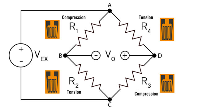
In some applications, the sensitivity of the system can be increased by using "half" or "full" bridges. For example, imagine a tube sticking out of a wall. A downward force is applied to the end of the tube, compressing its underside and stretching (tensioning) its upperside. The compressive and tensile strain measurements are equal. Using a strain gauge on either side (a half bridge) increases the sensitivity of the measurement, and automatically compensates for changes due to temperature. Similarly, mounting two gauges in compression and two in tension makes a full bridge which again increases the sensitivity.
Tips for Computerised Strain Measurement
A computerised system measures the bridge output voltage before the strain is applied, and then at regular intervals or whenever certain conditions apply.
8 Points to consider when Measuring Strain with a Computerised System
- As you need to measure the voltage across the bridge, you need two leads for each measurement. Your data acquisition interface should therefore accept differential inputs.
- You need to apply an excitation voltage to the bridge. Some hardware provides this excitation, but is limited in the number of strain gauges it can handle. Other hardware needs an external power supply, but will distribute the excitation voltage to many more strain gauges.
- We're assuming that the measured change in voltage is only due to the change in strain. However, other factors might also affect the reading, such as a change in the excitation voltage. This is of especial concern in long-term measurements where component values may drift with time and temperature. However, with suitable hardware and software like Windmill, a computerised system can measure the excitation at any time and then adjust the strain results for changes in the excitation voltage.
- The changes in voltage due to strain are tiny: measured in microvolts. Monitoring such small signal changes can often produce jitter in the readings from noise. For slow sampling you can counteract this with an integrating analogue-to-digital converter. By averaging the signal over 50 or 60 Hz the noise is rejected.
- The initial unstrained bridge measurement is often much larger than the change in signal due to strain. If this initial value is not accounted for, it restricts the resolution you can obtain - i.e. the smallest signal you can measure. A computerised system can zero or balance the bridge, nulling the offset of the initial voltage. So instead of measuring over a wide range, 0 to 0.5 V for example, you can choose a narrow range such as 0 to 0.01 V. (Each range is divided into a fixed number of steps. The smaller the range, the more precise the reading.)
- If your system is not capable of zeroing gauges, ensure that your analogue-to-digital converter has high enough resolution to give the dynamic signal range required. Even if you can zero the gauges, in some applications a high resolution converter might still be needed (16- or 18-bit for example).
- For high speed sampling of strain, it's useful if your data acquisition hardware has RAM storage of gain (range) and balance voltage for each bridge.
- When using quarter bridges (1 strain gauge) or half bridges (2 strain gauges) your hardware will typically provide high quality termination resistors. This makes it easy to permanently wire your signals to the hardware.
Hardware and Software to Measure Strain
We offer three packages to measure strain: the Microlink 751-SG, the Microlink 851-SG and the Microlink 770-SG
| Strain Measurement Package | Connection to Computer | Speed | Noise Reduction |
|---|---|---|---|
| Microlink 751-SG | USB | 10 Hz per channel | Integrating a-d converter |
| Microlink 851-SG | Ethernet / TCP-IP / Internet | 10 Hz per channel | Integrating a-d converter |
| Microlink 770-SG | USB | 100 kHz | By oversampling and averaging |
- Each USB or Ethernet unit provides 16 differential inputs and can thus monitor 16 strain gauges
- They can also measure temperature, pressure, voltage and current
- The 751-SG and the 851-SG can additionally switch up to 32 digital outputs, monitor up to 32 digital inputs and count events with up to 8 counters
- You can change and mix configurations
- You can connect up to eight units to one PC via USB, allowing 128 strain gauges to be monitored. An unlimited number can be connected with an Ethernet or Internet connection.
- No programming is required
- For portable, laptop, desktop and networked data acquisition
- Powered from the PC
- Low power consumption
- For 751 and 851 use Windmill software to select the resolution of the A-D converter (from 12- to 18-bits): choose high throughput or high resolution
- Automatic recalibration
- Comprehensive User Manual
- Free technical support for life
Strain gauges need an external excitation voltage to supply sufficient current to keep all the bridge circuits energised. The packages provide four sets of 16 screw terminals giving + and - excitation and signals for each of 16 bridges. Two 1 kOhm termination resistors are mounted in half bridge configuration whilst high quality 350 and 120 Ohm resistors can be provided for the completion of quarter bridges. The auxiliary channel of the a unit is used to monitor the excitation voltage. The analogue-to-digital converter can directly measure voltage imbalance.
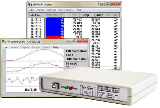
When a bridge input is selected the Windmill software automatically monitors excitation voltage and performs the bridge calculation to produce a reading in microstrain. This eliminates errors due to changes in excitation voltage (see point 3 above). You can also set a zero reference level (point 5 above) and monitor changes relative to that level.
With the Windmill Strain Measurement package you can configure individual channels to accept any one of the following inputs.
| voltage input | |
| quarter bridge | single strain gauge |
| half bridge | tensile + compressive strain gauge |
| half bridge | normal + transverse strain gauge |
| full bridge | two tensile + two compressive gauges |
| full bridge | two normal + two transverse gauges |
| full bridge | tensile normal + compressive normal + tensile transverse + compressive transverse gauge |
Ordering a Windmill Strain Measurment System
To purchase visit our on-line catalogue
Alternatively fill in this form or contact Windmill Software at the address below.