Monitor - ISSN 1472-0221
The Newsletter for Data Acquisition and Control
Issue 287 January 2023
You can download Monitor as a pdf file from https://www.windmill.co.uk/monitor/monitor287.pdf.
Contents
* Logging from I2C Devices
* Your Data Acquisition Questions Answered: Digital Displays & Charting
Logging from I2C Devices
Web link: https://www.windmill.co.uk/i2c.html
The I2C bus was developed by Philips Semiconductors. It was designed to provide communications between integrated circuits, though now it's used in many other applications.
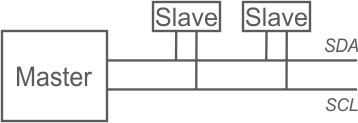
I2C uses just two wires: the clock wi= re (called SCL) and the data wire (called SDA).
All devices on the I2C bus are either a master or slave. There is generally just one master which controls the clock and data transfer. The slave devices respond to the master.
Initiating a Message
When the master wishes to talk to a slave it sends a start sequence, leaving SCL high and pulling SDA low.
Transferring Data
Data is transferred in sequences of 8 bits. The bits are placed on the data line starting with the Most Significant Bit (MSB). After every bit the clock line pulses high then low.
For every 8 bits transferred, the device receiving the data sends back an acknowledge bit (ACK). This means that there are 9 SCL clock pulses for each 8-bit byte of data.
Acknowledging the Data Transfer
If the receiving device sends back a low ACK bit, then it has received the data and is ready to accept another byte. If it sends back a high then it is indicating it cannot accept any further data and the master should terminate the transfer by sending a stop sequence.
Addressing I2C Devices
I2C addresses are most commonly 7 bits.
Even though the address is 7-bit, the master always sends 8 bits. The extra bit tells the slave whether data is being read or written. If the bit is 0 then the master is writing to the slave. If the bit is 1 then master is reading from the slave. The 7-bit address is placed in the upper 7 bits of the byte and the Read/Write (R/W) bit is in the LSB (Least Significant Bit). Thinking in 8-bit bytes, this means that even numbers are write addresses and odd numbers read addresses.
Working in decimal this addressing method can be confusing. Decimal 15 for example, is 00001111. But if you are sending 15 as a 7-bit address plus a read direction bit, you send 00011111 which is decimal 31.
Reading from and Writing to Registers
After sending the start sequence and the slave address, the next thing is to specify the register to which you want to write or from which you want to read. Some devices don't have any registers, some have several. After specifying the register the master can send the data. If more data arrives than will fit in the register, the slave just allocates it to the next register.
Stopping sending Data
At the end of the transfer the master sends the stop sequence.
Software to communicate with I2C Devices
Windmill software lets you communicate with I2C devices. Email monitor@windmillsoftware for your free copy.
Your Data Acquisition Questions Answered: Digital Displays & Charting
Question
"We are looking at making a 16 channel strain gage measurement system for a customer of ours, and I notice that one of your products would suit this purpose very well the Microlink 751-SG.
We have used one of your products and software in the past many years ago for another customer.
Does your software allow the user to create a an individual digital display for each channel as well as charting each channel, and can you switch between the screens?"
Answer
You can use Windmill to create a digital display for one or more channels, and also create multiple displays for different channels. You can do the same with real-time charts (up to 4 channels on each display. The software is included with the hardware package.

Read more about the Microlink 751-SG strain measurement package.